
Part 1 – Introduction
Part 2 – Woodworks
Part 3 – Control Panel
Part 4 – CRT Assembly
TBD: Part 5 – Electric Assembly
TBD: Part 6 – Software Setup

Finished Assembly
To be honest, this was the part I started with. I don’t really remember what gave me the inspiration, but the first thing I did was to design my panel. I downloaded Inkscape, got a grip on an existing panel layout that I liked and made a deep dive into the Slagcoin button tutorials. I posted my first design to the wonderful MAME Arcade group on Facebook and got a lot of feedback. Some of this I included in the follow-up design, like “you won’t need mouse buttons” or “you will need two coin buttons”, but to be honest, the best thing is – do a rough sketch, take some excess wood, buy a button set on Ebay and do a prototype.
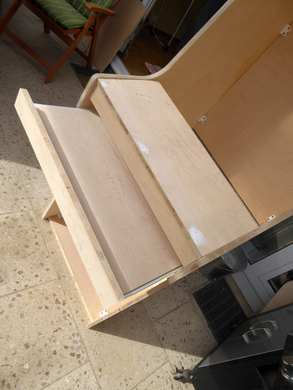
Tray
Hardcore players should do a bit of research on Happ, iPac and other well-known brands, but for a leisure-gamer like me, I really didn’t care about some milliseconds of lag or the sound of the buttons. Just make sure, you test your prototype under realistic conditions. Try some OS situations with just a trackball and keyboard for example – and you will see, you WANT *two* mousebuttons on the panel – those can be used in the emulator as well, of course, and do not need to have a unique position. Furthermore – check your software first! Some emulators or frontends have a “shift”-button assigning the joystick to control sound or paging rather than two up/down buttons, so some of your ideas might be bound to failure right from the start.
A tutorial on how to design a panel with Inkscape can be found here.
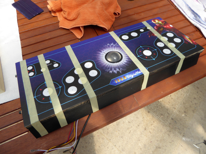
Decal
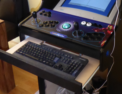
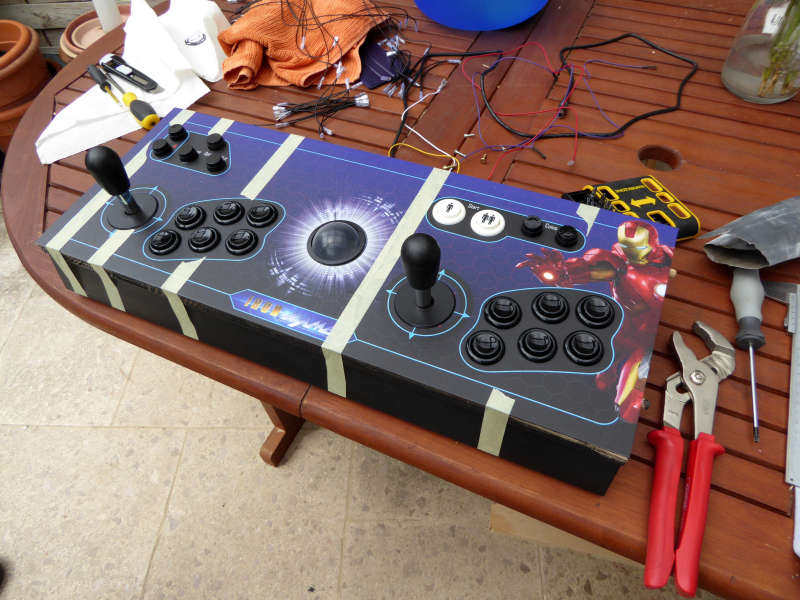
My control panel is set up in two parts – the upper, holding all the controls, including a trackball, the lower is an extendable tray, holding the volume control, the PC start button (I have an ATX Power source that needs a signal) and the keyboard. I already had a Logitech Sound System with subwoofer and quad-channel from ten years ago, that had a volume control for the desktop, so this was a perfect component for my machine.
Be aware, that you might want to play pinball games, so make sure you have at least one button on each side of the cabinet – I later found out, that two are even better (one each for nudging). The good news is – these can be wired parallel to the standard arcade buttons, so you won’t need extra channels, the bad news is – I couldn’t coax PinMAME to recognize my second controller, so I had to rewire the right buttons to the first controller. Talk about trial and error.
One most important issue, if you are using flipper buttons: Make sure, that the length of the buttons does not collide with your arcade layout on the top. To play conveniently you are not able to put them low enough to have them out of the way, so make sure, your arcade controls leave enough space to the sides of the cabinet. Mine do just fit barely – and that was sheer luck and I had to bend the connectors out of the way.
Drilling
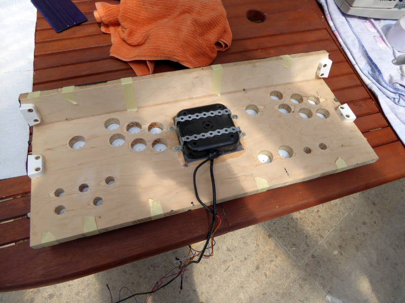
Drilled
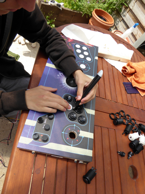
The buttons and the joysticks are easy – use a matching Forstner drill bit or buy an adjustable center drill bit (like I did). Be aware, that most joysticks and trackballs are made for 3mm steel mounts, so be prepared to do some routing if you use 18mm multiplex. In my case, the joysticks had sticks that were long enough, only the trackball gave me some thoughts – I ended up making a hole for the complete trackball casing, securing the case with perforated metal strips from below and filling the seams with silicone. I was afraid of drilling through the decals (the plastic might tear) and did the drilling first, cutting the holes into the decal with a model knife (in fact, my son did it). Since most of the components have covering edges anyway, one can afford a bit of inaccuracy.
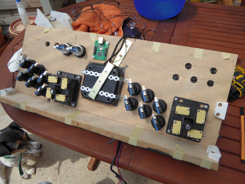
When doing the wiring, make sure, that you attach the PCB to the panel at the very end of the process – otherwise you will probably experience short wires or other kinds of collisions. Don’t forget the flipper-buttons – you will need wires for this that will be long enough to connect when the panel is mounted.
Mounting
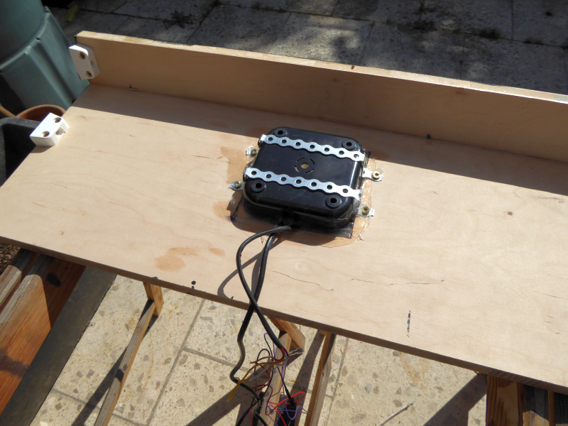
Trackball
Talking about mounting: At first I had the obvious wooden dowels and furniture connectors – a setup that gave me the creeps, whenever I had to rewire something or when I added the second set of flipper buttons. So I ended up drilling through the sides (eek!), using two screws as “hinges” on the upper part of the arcade panel and removing the connecting plastic parts of the furniture connectors, so they just acted as “stoppers” for the movement – voila, a panel that can be opened like a car’s hood. Much better.
Finally, I checked my wiring against the “Game Controllers” plugin of XP’s Control Panel. Worked like a charm. Tip: Jot down some quick notes of the key’s assignments – there are some emulators that are not so friendly to just let you push the right button.
Cutout
Mounted Parts
Mounted Decal
[…] 1 – Introduction Part 2 – Woodworks Part 3 – Control Panel Part 4 – CRT Assembly TBD: Part 5 – Electric Assembly TBD: Part 6 – Software […]